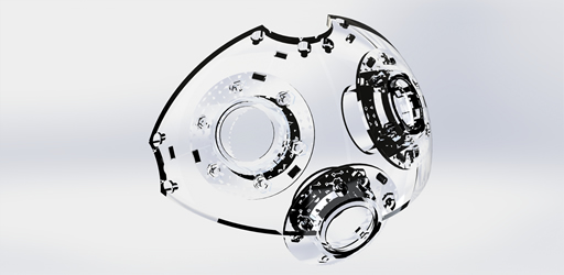

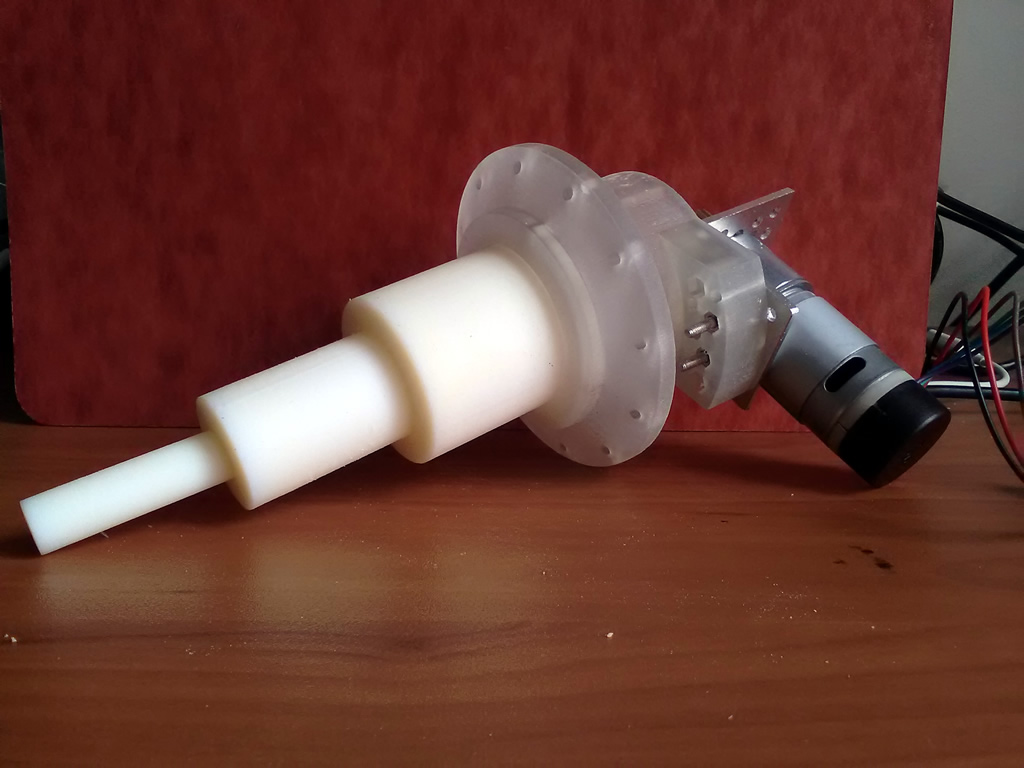
The telescopic actuator consists of four levels, in the small particle robot with D = 130mm, the actuators can be extended up to l = 64mm from the top of its base level. The length of the actuator when extended is L = 89mm and when contracted is equal to the base height baseheight = 25mm with an extension ratio of 1:3.56.
Telescopic actuator with articulated rigid rack.
The base level of the telescopic actuator is 3D printed with rigid material in order to support all the telescopic levels and connections with the outer shell parts. The following three levels in the telescopic actuator are combinations of 3D printer materials: rigid 75% and flexible 25% in order to withstand hits, similar to the outer shell parts.
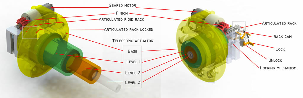
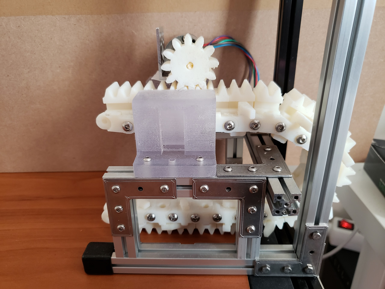
The telescopic actuator integrates a 3D printed rack and metallic pinion gearbox to extend and contract the levels. A geared motor attached to the telescopic’s base level isthe actuation unit ”pinion”, which drives the articulated rack attached to the top level of the telescopic arrangement.
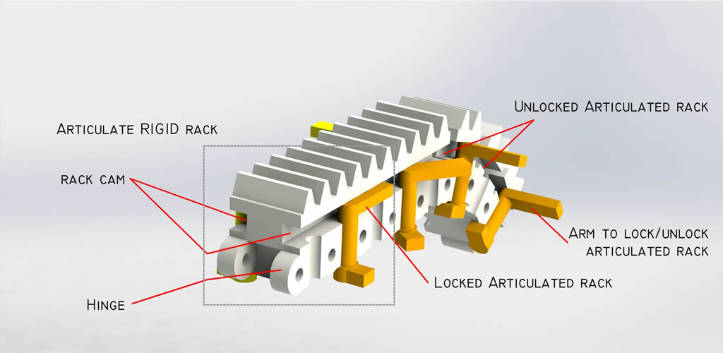
Each articulated rack consists of a couple of gear-teeth, a rack-slot on the sides, a pin with a couple of arms to lock/unlock the articulations and a hinge on both ends for linking the rack articulations.
1) Gear-teeth: The articulations can be set with n numberof gear-teeth. However, when the articulations are folded, the more gear-teeth per articulation will lead to a lower degree of compression. The optimal solution for folding the articulated rack to a minimum is with a single gear-tooth per articulation. However, in the presented prototype, the articulations are set toa couple of gear-teeth. Since, it is easier to construct, arrange and have a good compression ratio.
2) Rack-slot and pin with arms: Each articulated rack has a rectangular and cylindrical slots on each side. A pin is inserted in the cylindrical slot, this pin consists of a cylindrical segment with a couple of arms, each attached on each pin’s edge. The arms are oriented 90° from each other, one is always parallel to the rack extension axis and the other is perpendicular to it, pointing out from the rack gear. The arm ARML is used for locking the articulated rack, while for unlocking the arm ARMU is used.
3) Hinge on both ends: The articulated racks integrate a hinge connector on both ends to interlock the articulations and create a longer rack. The hinge connectors are also use for attaching a cover to the cylindrical pin with arms, so it is always trapped when rotating.

Articulated rackcomponents. 3D printed articulated rack prototype with locked (rigid) and unlocked(foldable) segments. Articulated rack components: Pin cover, cylindrical pin with arms, gear-teeth, 3D model of a couple articulations (right)
4) Telescopic holder: Besides the telescopic base level which integrates the gear-motor, an extra holder is required to guide the articulated rack and transform it from rigid to foldable and vice-versa. The holder integrates a couple of guides, one for each arm of the pin (ARML and ARMU)for locking or unlocking the rack articulations
Articulated rack locking: If the pinion attached to the gear-motor rotates clockwise, it will move the articulated racks out from the actuator, and the telescopic holder will guide the pin’s arm ARML to fit inside the rack’s slot, changing the articulation properties from foldable to rigid.
Articulated rack unlocking: If the pinion rotates counterclockwise, it will move the articulated racks inside the actuator, so the guides from the telescopic holder rotates the ARMU and consequently rotating the ARML releasing it from the rack’s slot, changing the articulation properties from rigid to foldable.

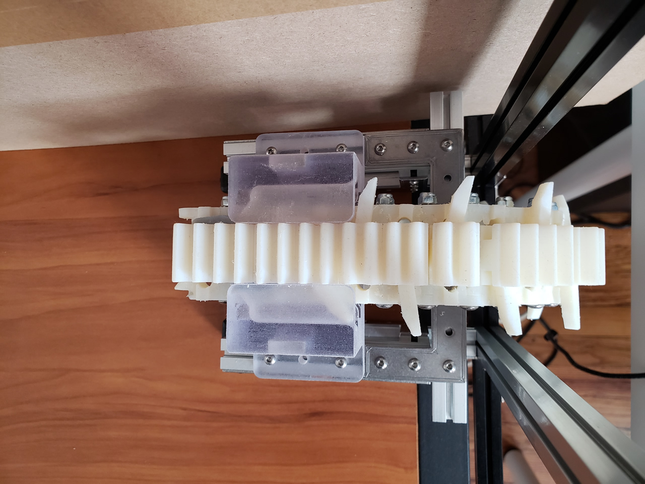
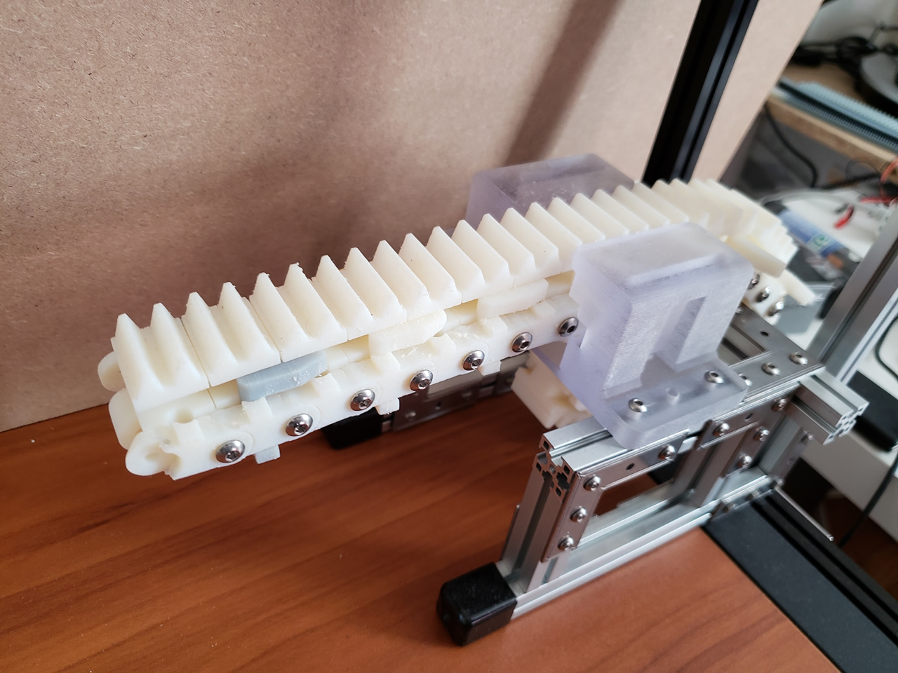
a) The articulated rack is changed from foldable to rigid when the geared motor (pinion) rotates clockwise, moving the articulated rack out fromthe telescopic actuator. The inner guides from the telescopic holder guide the arm ARML to fit in the rack’s slot. b) The articulated rack is changed from rigid to foldable when the geared motor (pinion) rotates counter clockwise, moving the articulated rack inside the telescopic actuator. The inner guides from the telescopic holder guide the arm ARMU to rotate and consequently moves the arm ARML out of the rack’s slot (top). 3D printed prototype with rigid and foldable parts before and after passing through the guides from the telescopic holder (bottom).
How it works - articulated rigid rack (top). Telescopic actuator with actuation system (bottom).