
The first step is homing. This step utilizes a tracking system to assist in guiding the AUV into the dock. This system is activated once the AUV is within a close range of distance to the docking station. In order to measure the distance between the AUV and a docking station, the following sensors can be applied:
1) Optics. The optical approach can be thermal [15] or visual [10] [16] with a range up to the visibility of the target (1m to 15m) and high accuracy in the milimeter range.
2) Electromagnets. The electromagnetic solution is able to provide the orentation and is able function within a range up to 10m with the accuracy of ±0.1m [7].
3) Acoustic. This solution consists of an ultra short base line (USBL) with a range up to 30m with the accuracy of ±0.2m. [5] [6] [9] [14].
1) Infrared sensor.
We integrated an array of IR LEDs on the pin (male) and an array of IR photodiodes on the funnel (female) to detect the IR LEDs. The guiding with this sensors works for a distance 1000mm - 500mm. With this framework we are able to know only the position. However, we can give different frequencies to each funnel-pin pair to differenciate them and identify them.
The pins in this case require power to light up the IR LEDs, hence, the docking station requires to be powered.
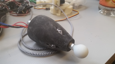
Pin with integrated IR LEDs (left). Funnel with IR sensors (right)
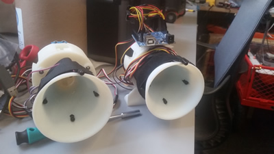
In the video, if only the right funnel detects IR, it keeps moving to the right until the left funnel detets its respective IR LEDs. When both funnels detect the IR LED, this means that the roboat is centered for latching.
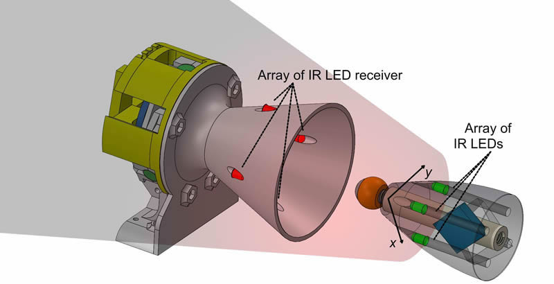
Infrared guiding 3D model (left). Guiding system based on infrared (right).
2) Infrared camera.
In this configuration the IR elements are not integrated in the latching elements (pin neither funnel). Instead an onboard IR camera tries to find and external IR LEDs tag. The camera is a IR stereo camera with low field of view, meaning it can only detect IR upto 500mm. This configuration requires that the onboard computer process the pose estimation, instead of the previous version with IR LEDs and IR sensor, where the processing is performed by the microcontroller.
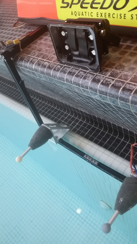
Roboat with integrated IR camera (left). IR LED array (right)
Estimating the camera pose from a set of 3D-to-2D point correspondences is known as Perspective from n Points (PnP) (or resection). The minimal case involves three 3D-to-2D correspondences. This is called Perspective from 3 Points (P3P) and returns four solutions.
Robustness can be increased if the LEDs are visible from as many view points as possible. Since we are using infrared LEDs whose wavelength matches the infrared-pass filter in the camera, they appear very bright in the image compared to their environment. Thus, a thresholding function is sufficient to detect the LEDs. With at least four LEDs on the target object and the corresponding detections in the camera image, we can compute the 6 DOF pose of the target object with respect to the camera. Our system can also handle more than four LEDs on the target object.
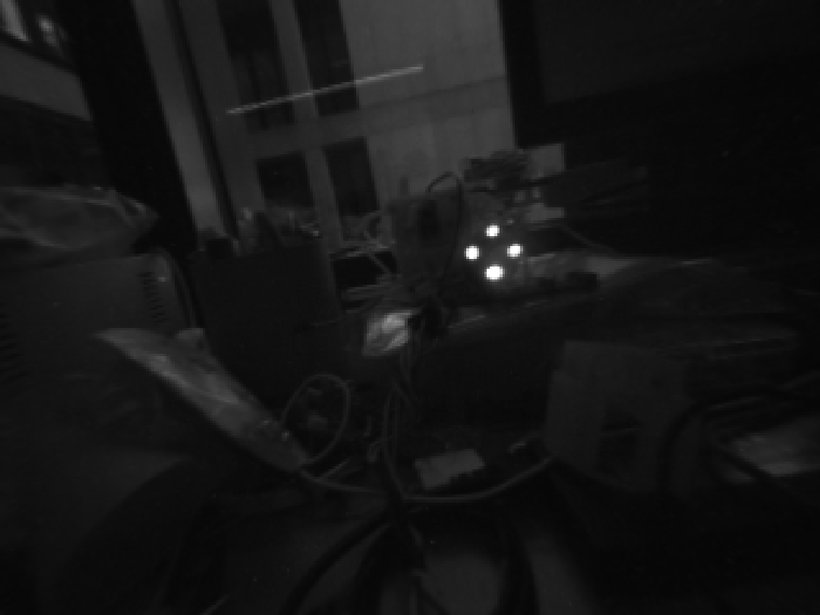
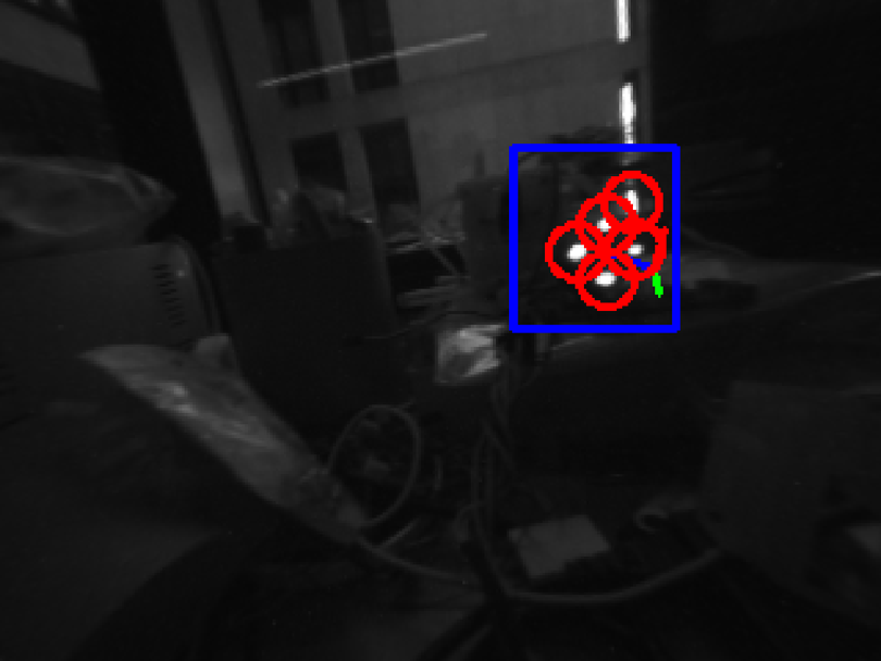
IR camera (left). Detection of four IR LEDs (right)
3) Camera - Tag.
Fiducial markers are commonly use in computer vision (CV) and augmented reality (AR) aplications for detection and identification. In robotic applications, fiducial markers have been of crucial importance for obtaining an accurate pose estimation of the marker. Since, estimating the tag’s 6 Degrees of Freedom (DOF) can lead a robotic arm to grab an item, or guide an autonomous robotic boat to a docking station or to latch another robot, see Figure 1.
There are different families of markers, with circular and squared shapes, and color base [4]. Circular tags such as Intersense [11] and Rune tags [3] provide accurate pose estimation in short distances with a high computational cost. While, squared fiducial tags such as ARTags [6], ARToolkit [10], ArUco [7], AprilTags [12] and AprilTag2 [14] have a low computational cost and can be detected from a further distance.
In robotics, the AprilTags framework has been prefered for having a lower false positive rate and higher detection rates in challenging viewing angles at further distances. However, AprilTags marker systems rely on RGB image space for detection and pose estimation, which is susceptible to the perspective ambiguity noise from sub-pixel detections in their corner locations. Resulting in rotational errors, making the pose estimation challenging without additional information [9].
Who uses AprilTags
Boston dynamics, creates humanoid robots for real case scenarios. MIT in multiple laboratories.
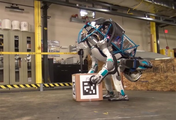
Atlas robot integrates AprilTags to identify and detect the pose estimation (position and orientation) of an object (Photo ®Boston Dynamics).
Among squared fiducial marker systems, AprilTags [12] [14] perform the best when detecting smaller markers, in high angle inclination and in different lighting levels [5]. This is the reason of their popularity in the robotics community.
Roboat guided by tag located on docking station.
The figure shows the AprilTags framework. If the camera is positioned in front of the tag, the lateral distance dy and angle are zero. While the longitudinal distance between the camera and tag is dx in the X-axis. If the camera changes its position with the same orientation, then the lateral distance dy reflects its change in position on the Y-axis, dx is the same longitudinal distance and angle = 0. If the camera in that position changes its orientation to face the tag, then the lateral distance dy = 0 and the angle reading becomes the true angle between the camera and tag.
Roboat guided by tag located on a docked roboat.
Roboat guided by tag located on a balancing roboat in extreme waves at sailing Pavillion MIT, Charles River.
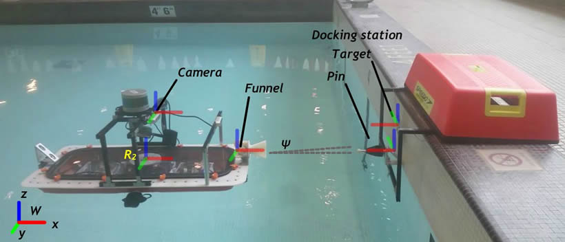
In order to latch the roboat to a dock or to another robotic boat, a guiding system has been developed. This guiding controller is activated, overriding the driving control system, when the boats are set to latch and the detected distance between them is less than 1500mm.
Guiding to a dock
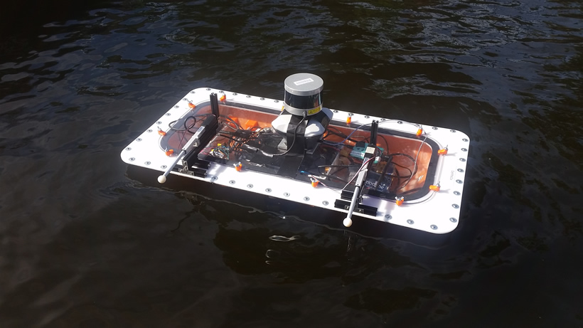
On the docks there are passive elements with only a permanent magnet as device to help direct the roboat for latching. In this configuration, the active element (on-board the roboat) activates its 3D magnetometer to find the position that leads to the passive element on the dock. To do so, the magnetometer is configured as follows: The x and y axis corners of the magnetometer are pointing outwards so when reaching to the magnetic field of the permanent magnet in the passive part, the position is related to a 2D plane and corrections can be made by the guiding controller. In other words, it is able to know the position of the magnet, whether it is located on the left or right of the pin.
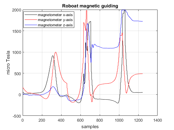
Magnetic field : The magnetometer integrated in the system is the BNO055, able to detect the magnetic field strength vector (20Hz) in three axis of magnetic field sensing in micro Tesla (microT). The permanent magnet is a NdFeB magnet with magnetization N42, and strength of 7:7kg (approx. 75.5N). The next figure shows the relation between the distance in mm and microTesla
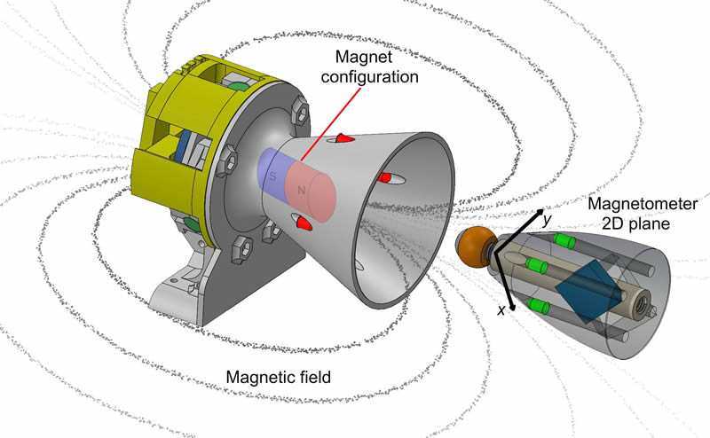
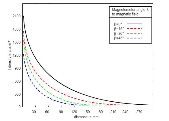
Guiding system based on magnetic field (left). Magnetic field detection by the 3 axis magnetometer in different inclination angles (B=0Deg B=15Deg B=30Deg B=45Deg) (right)
Guiding to a roboat
In the roboat to roboat latching, both parts are active and can be powered. The male part is now powered and activates its electromagnet (with similar characteristics as the permanent magnet with 75N strength), while the female part activates its 3 axis magnetometer. Analogous to the previous case, the magnetometer helps to infer the position, while the roboats communicate IMU (Inertial Measurement Unit) data, in specific their heading angle to keep the roboats parallel to each other when guiding,
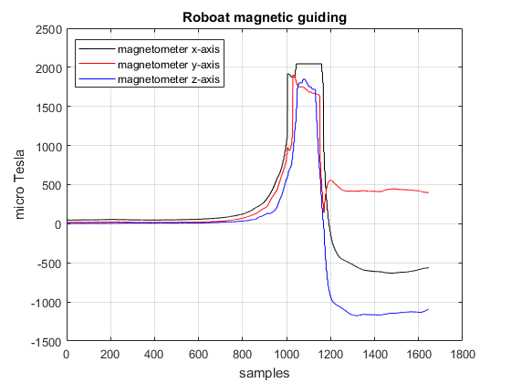
Magnetic field when roboat moves towards the field, from the front (left) and from the side (right).
Roboat moving towards the magnetic field.
The Lidar is good for medium distance perception and navigation (2m to 100m), it gives an error in position of ±100mm. Thus, it cannot be used for accurate positioning in short distance < 2m.

Roboat with lidar for perception and navigation 3D model (left). Guiding system based on lidar ±100mm (right).
The GPS is used for global navigation with error in position > lidar (±200mm). Hence, it is not a solution for latching with high precision where the error is required to be <40mm.
Guiding system based on GPS ±1000mm (left). Roboat with GPS and lidar (right).